Choosing the wrong extruder screen is one of the most common — and most costly — mistakes in polymer extrusion. An undersized mesh allows contaminants to pass through and damage downstream equipment. An overly fine screen creates excessive pressure drop, reduces throughput, and shortens filter life. Getting the specification right from the start saves material, time, and operational cost.
This guide walks through every factor you need to consider: mesh count, micron rating, layer configuration, screen pack type, material, and equipment compatibility. By the end, you will have a clear framework for selecting the correct extruder screen for any polymer, any process, and any screen changer.
What Is an Extruder Screen?
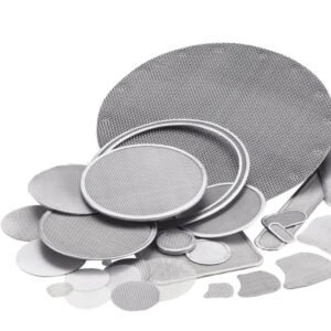
An extruder screen (also called a screen pack, melt filter screen, or extrusion filter screen) is a woven wire mesh disc or assembly installed in a polymer extruder, between the screw tip and the die, to filter contaminants from molten plastic, rubber, or other polymer materials. It is held in place by a breaker plate and functions as the primary mechanical filtration barrier in the extrusion process.
Extruder screens serve three core functions:
- Filtration — removing solid contaminants such as unmelted particles, carbon black agglomerates, gels, wood fibers, metal fragments, and other foreign materials from the melt stream
- Backpressure generation — creating resistance that promotes thorough melting, homogenizes the melt, and stabilizes screw output
- Flow homogenization — straightening the rotational flow exiting the screw into a uniform axial flow before it enters the die
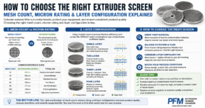
Step 1: Understand Mesh Count and Micron Rating
What Is Mesh Count?
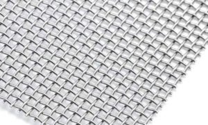
Mesh count is the number of wires per linear inch in a woven wire mesh. A 20-mesh screen has 20 wires per inch; a 200-mesh screen has 200 wires per inch. Higher mesh count means finer wire spacing and therefore smaller openings between the wires.
What Is Micron Rating?
Micron rating (μm) refers to the nominal aperture size — the size of the square opening between the wires, measured in micrometers (microns). One micron equals one thousandth of a millimeter. A screen with a 150-micron aperture will retain particles larger than approximately 150 μm.
How Mesh Count and Micron Rating Relate
The aperture size depends on both the mesh count and the wire diameter. Two screens can have the same mesh count but different aperture sizes if the wire diameters differ. For this reason, always specify the aperture size in microns rather than relying on mesh count alone when precision filtration is required.
The following table shows the typical relationship between mesh count and approximate aperture size for standard plain-weave wire mesh:
| Mesh Count (per inch) | Approx. Aperture (microns) | Filtration Class | Typical Use |
|---|---|---|---|
| 10 – 20 | 840 – 2000 μm | Coarse | Support / backing layer, heavy regrind pre-filtration |
| 20 – 40 | 420 – 840 μm | Coarse–Medium | PE/PP pipe, profile, recycled pelletizing |
| 40 – 80 | 200 – 420 μm | Medium | General-purpose PE/PP/PVC extrusion |
| 80 – 120 | 125 – 200 μm | Medium–Fine | Blown film, cast film, sheet extrusion |
| 120 – 200 | 75 – 125 μm | Fine | Optical film, technical film, compounding |
| 200 – 325 | 45 – 75 μm | Very Fine | PET fiber spinning, PA filament, specialty film |
| 325 – 500 | 25 – 45 μm | Ultra Fine | High-clarity optical applications, specialty polymers |
Step 2: Determine Your Required Filtration Fineness
By Polymer and Application
The correct filtration fineness is determined by the cleanliness level required in the final product, the contamination level in the raw material, and the tolerance of downstream equipment (dies, spinnerets, roller surfaces) to contamination. The table below provides starting-point recommendations:
| Application | Polymer | Recommended Fineness | Notes |
|---|---|---|---|
| Pipe & profile extrusion | PVC, HDPE, PP-R | 40 – 80 mesh (200 – 420 μm) | Higher pressure resistance needed for PVC |
| Blown film / cast film | LLDPE, LDPE, PP | 80 – 150 mesh (100 – 200 μm) | Gel control is critical for thin films |
| Sheet extrusion | PET, PS, PP | 80 – 120 mesh (125 – 200 μm) | Surface quality demands consistent filtration |
| Fiber & filament spinning | PET, PA, PP | 200 – 325 mesh (45 – 75 μm) | Spinneret protection is the primary driver |
| Pelletizing — virgin resin | PP, PE, ABS | 40 – 80 mesh (200 – 420 μm) | Low contamination; focus on throughput |
| Pelletizing — recycled material | Mixed regrind | 20 – 60 mesh (250 – 840 μm) | High contamination; multi-layer packs essential |
| Masterbatch & compounding | PE, PP + fillers | 60 – 120 mesh (125 – 250 μm) | Filler particles can clog fine screens rapidly |
| Engineering polymer extrusion | TPU, PA, POM, PEEK | 100 – 200 mesh (75 – 150 μm) | Corrosion-resistant materials often required |
| Rubber extrusion | EPDM, silicone, NR | 20 – 60 mesh (250 – 840 μm) | High viscosity requires lower pressure drop |
By Contamination Type
The nature of the contamination also influences screen selection. Hard inorganic contaminants (metal particles, sand, glass) require a fine filtration mesh to prevent die damage. Soft organic contaminants (unmelted polymer, gels, carbon deposits) require a mesh fine enough to retain them but coarse enough to avoid rapid fouling. In heavily contaminated recycled material streams, a coarse pre-filter layer is always recommended upstream of the fine filtration layer.
Step 3: Choose the Right Screen Pack Type
Once filtration fineness is determined, the next decision is the physical form of the screen pack. The five main types each suit different equipment configurations and production requirements.
Welded Extruder Screen Packs
Multiple mesh layers are spot-welded together at the edges to form a stable, integrated pack. The layers are bonded without a frame, relying on the breaker plate for edge support. Welded packs are the most widely used type globally, suitable for manual, slide plate, and piston-type screen changers. They are cost-effective, easy to handle, and available in the widest range of sizes and mesh combinations.
Framed Extruder Screen Packs
A rigid aluminum or stainless steel outer ring is added around the mesh assembly. The frame provides precise dimensional control, improves edge sealing against the breaker plate, and makes installation faster and more reliable. Framed packs are preferred in high-pressure applications, in processes where screen misalignment leads to quality defects, and where operator handling efficiency is important.
Pleated Extruder Screen Packs
The mesh is folded into a pleated configuration before assembly, increasing the effective filtration area by a factor of 3 to 5 compared to a flat screen of the same outer diameter. Pleated packs deliver significantly lower pressure drop at the same throughput, longer service intervals between screen changes, and better performance with fine-mesh filtration where flat screens foul rapidly. They are the preferred choice for PET fiber, PA, and high-value film applications.
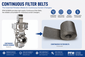
Continuous Filter Belts
Rather than a disc-shaped screen, a continuous roll of woven wire mesh is fed through a belt-type screen changer. The belt advances automatically as contamination builds up, providing uninterrupted filtration without production stops. Continuous belts are used in high-output lines where manual screen changes would cause unacceptable downtime, such as high-speed PE blown film and post-consumer recycling lines.
Cylindrical Extruder Screens
A cylindrical mesh element is used in candle filter housings and spin-pack assemblies. The large cylindrical filtration surface provides very high dirt-holding capacity and uniform flow distribution. Cylindrical screens are standard in PET fiber spinning and other applications using candle filter melt filtration systems.
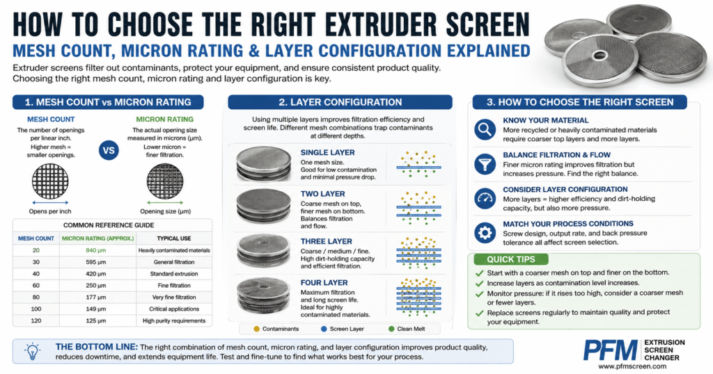
Step 4: Select the Right Layer Configuration
A screen pack’s performance depends not only on the filtration mesh but also on the supporting layers around it. A multi-layer configuration distributes mechanical load, prevents the fine mesh from deforming under pressure, and improves dirt-holding capacity.
Layer Functions
- Support layer (coarse, e.g., 20–40 mesh) — provides structural rigidity and prevents deformation of the fine filtration layer under melt pressure. Placed on the downstream (die) side of the pack.
- Pre-filtration layer (medium, e.g., 40–80 mesh) — captures larger contaminants before they reach the fine filtration layer, significantly extending service life.
- Filtration layer (fine, e.g., 100–325 mesh) — the primary filtration element that determines the actual particle retention size.
- Distribution layer (medium, optional) — placed on the upstream side to distribute melt flow evenly across the filtration layer and prevent channeling.
Layer Configuration Guide
| Configuration | Typical Layer Stack (upstream → downstream) | Best For |
|---|---|---|
| Single layer | 1× filtration mesh | Low-pressure, coarse filtration, testing |
| 2-layer | Filtration + support | Simple processes, moderate pressures |
| 3-layer (most common) | Pre-filter + filtration + support | General extrusion, blown film, pipe, pelletizing |
| 4-layer | Pre-filter + filtration + intermediate + support | High-pressure applications, recycled materials |
| 5-layer and above | Distribution + pre-filter + fine filtration + intermediate + support | Fine filtration (fiber, optical film), heavily contaminated feedstocks |
The standard 3-layer configuration — coarse pre-filter / fine filtration mesh / coarse support layer — is the correct starting point for most general extrusion applications. Moving to 4- or 5-layer configurations is recommended when operating pressures exceed 250 bar, when the filtration mesh is finer than 100 mesh, or when feedstock contamination levels are high.
Step 5: Match Screen Dimensions to Your Equipment
Even the best screen specification is useless if the screen does not fit correctly. Dimensional mismatches cause melt bypass around the screen, uneven pressure distribution, and premature seal failure. When specifying extruder screen dimensions, the following parameters must be confirmed:
- Outer diameter (OD) — must match the breaker plate bore precisely. Common sizes range from 20 mm to over 400 mm, but non-standard sizes are frequent in older or custom-built equipment.
- Inner diameter (ID) — relevant for ring-type or framed screens; must clear the breaker plate center post if present.
- Thickness — determined by the number of layers and wire diameters; must fit within the screen seat depth without gaps or excessive compression.
- Frame material and ring type — aluminum frames are standard for moderate temperatures; stainless steel rings are required above 280°C or in corrosive environments.
For screen changers (slide plate, piston, or continuous belt types), always confirm the screen format required by the screen changer manufacturer. Some screen changers require screens with specific cutout shapes, notches, or edge treatments. PFM SCREEN supplies screens matched to all major screen changer brands including Nordson BKG, Kreyenborg, Gneuss, Maag, and Ettlinger.
Step 6: Select the Right Mesh Material
For most standard polymer extrusion applications — PE, PP, PET, PVC, ABS, PS at temperatures below 300°C — stainless steel 316L is the correct material choice. SS316L offers excellent corrosion resistance, good tensile strength at elevated temperatures, and compatibility with virtually all standard thermoplastics. SS304 is a cost-effective alternative where the slightly lower corrosion resistance of 304 vs. 316L is acceptable.
Specialty materials are required in the following cases:
- Halogenated polymers (PVC, PVDF, PTFE) — these release HCl or HF during processing, which corrodes standard stainless steel. Nickel, Monel, or Inconel alloy screens are recommended.
- High-temperature engineering polymers (PEEK, PPS, above 350°C) — Inconel 600 or 625 provides superior oxidation resistance at extreme temperatures.
- Abrasive filled compounds (glass-filled PA, mineral-filled PP) — harder wire materials or increased wire diameter improve abrasion resistance and extend service life.
- Food-contact applications — SS316L is required; all materials must comply with applicable food-contact regulations (FDA, EU 10/2011).
A detailed material selection guide for extruder screens is covered in a separate article in this series.
Common Mistakes When Selecting Extruder Screens
- Specifying mesh count without aperture size — mesh count alone does not define filtration fineness. Always specify the aperture in microns for precision applications.
- Using a single-layer screen at high pressure — a single fine-mesh layer without support will deform or rupture under melt pressure above approximately 150 bar. Always use a support layer.
- Using too fine a mesh for recycled materials — fine screens blind rapidly when processing highly contaminated regrind. Start with a coarser pre-filter and use a multi-layer pack to extend service life.
- Ignoring dimensional tolerances — even a 0.5 mm discrepancy in outer diameter can cause melt bypass. Always measure the breaker plate bore directly rather than relying on nominal equipment specifications.
- Selecting material based on cost alone — using SS304 in a halogenated polymer application or a standard stainless screen at extreme temperatures leads to rapid screen failure, contamination of the melt, and potential equipment damage.
Quick Reference: Extruder Screen Selection Summary
| Parameter | What to Specify | Key Considerations |
|---|---|---|
| Filtration fineness | Aperture size in microns | Based on polymer, contamination level, product quality requirement |
| Screen pack type | Welded / framed / pleated / belt / cylindrical | Determined by screen changer type and output requirements |
| Layer configuration | Number of layers + mesh count per layer | Start with 3-layer; move to 4–5 for high pressure or fine filtration |
| Dimensions | OD, ID (if applicable), thickness | Measure breaker plate bore directly; confirm screen changer format |
| Material | Wire mesh alloy + frame/ring material | SS316L for most applications; specialty alloys for corrosive or extreme-temperature polymers |
Conclusion
Extruder screen selection is a multi-variable decision that directly affects melt quality, process stability, and operating cost. The correct approach is to define the filtration fineness required by the application first, then select the screen pack type and layer configuration to meet both the filtration and mechanical requirements, and finally confirm dimensional and material compatibility with the specific equipment and polymer being processed.
If you are unsure about the correct specification for your process, PFM SCREEN’s technical team can assist with screen selection based on your polymer, throughput, screen changer model, and quality requirements. Contact us with your process parameters and we will recommend the optimal screen pack configuration.
For more on extruder screens, see our full product range: Extruder Screens & Screen Packs.